Via letsmakerobots.com I have been contacted by marcmart.com an electronics distributor. They asked me about writing a review for a Makeblock product. So I took the chance to write this review.
httpv://www.youtube.com/watch?v=4WdDitRFxC0

Robotik, Elektronik, Arduino und mehr
Via letsmakerobots.com I have been contacted by marcmart.com an electronics distributor. They asked me about writing a review for a Makeblock product. So I took the chance to write this review.
httpv://www.youtube.com/watch?v=4WdDitRFxC0
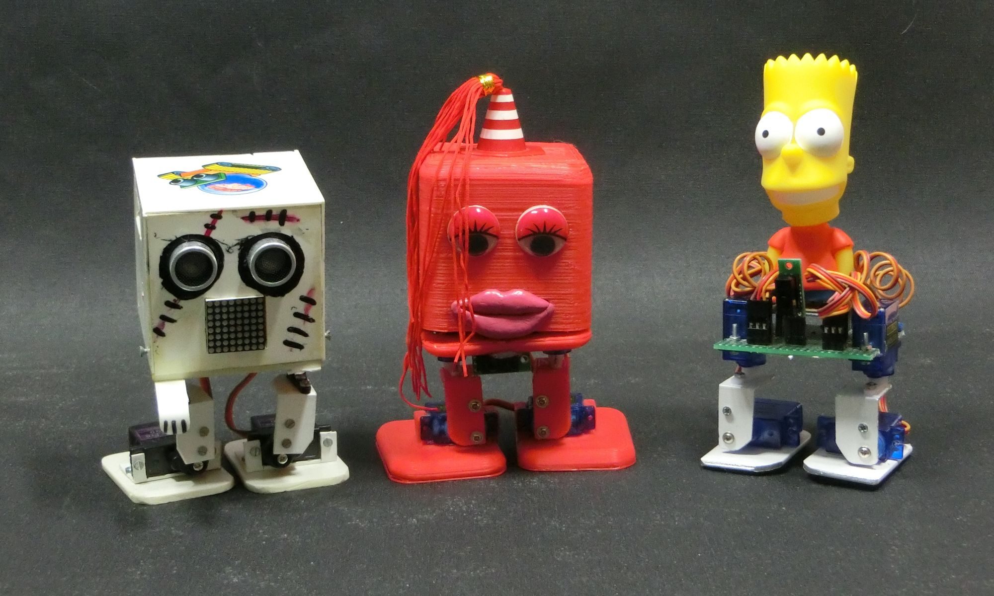
This is ‚Little Red BoBette‘, another member of BoBs army. The name is taken from an old Prince title, ‚Little Red Corvette‘. BoBette is my first female robot. She is the bride of FrankenBoB.
This is IOIO-Rover, my actual robot project. I has taken a long time to get it working, due to hardware and software problems. The project started 8 month ago. I’m not working full time on it. And most of the time I spend to learn Java and how to write Android apps.
The IOIO-Rover will be used as our new house guard. It can drive around through our home when nobodys home and will check for intruders. Later on I hope it will be possible to start the robot with a phone call and watch live video via Skype or a G+ hangout.
This tutorial shows the use of timers and interrupts for Arduino boards. As Arduino programmer you will have used timers and interrupts without knowledge, because all the low level hardware stuff is hidden by the Arduino API.
Drifter is based on a cheap RC toy car I found at Toys’r’us, named ‚Fast lane Monster Drift‘. I think it’s the same model Frits has been used in an episode of TLIHR. It doesn’t work well, you get what you pay for. But it is a good hacking platform. There is no much space left for additional electronics, but a Arduino Pro Mini fits very well on the rear axle.
The onboard electronic is as usual very primitive. A PCB with a RC receiver IC, 2 H-Bridges for drive and steering motor, and a voltage regulator (3,3V). Lucky me I found the control signals going from the RC receiver to the motor drivers and an easy way to cut these connectors and put the Arduino between. That way I can use the existing remote control. 4 Inputs and 4 outputs were needed (forward, backward, left and right). As outputs the PWM capable pins 5,6,9,10 has been used to give the possibility of smooth movements, instead full speed drive and steering from the original hardware.
Here is the complete schematic and wiring made with Fritzing.
The Remote control is used as a mode selector. On power up the Arduino reads the remote and executes the selected mode of operation.
Further development:
To make the car autonomous it needs a ultrasonic sensor. Unfortunately I only have a HC-SR04 ultrasonic sensor ready, witch is a 5V device. The existing electronics and the Arduino are 3.3V powered. So the HC-SR04 needs to be replaced with a SRF01 or Maxbotix sensor. Both work with 3.3V.
I found an interesting project of our fellow member DuaneB about using a Gyro sensor to smooth the movement of a RC car. This might be a way to make autonomous drifting possible.
Lets see how far I can get.
Videos:
httpv://www.youtube.com/watch?v=ToJJEQ3pxe4