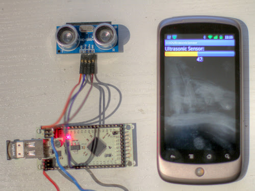
This is part 1 of a series of robotics tutorials with the IOIO controller. It shows how to connect a cheap ultrasonic sensor to the IOIO board and how to write a Android program to read the sensor.

Introduction
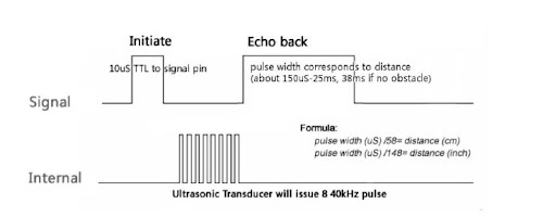
Ultrasonic sensors are very common in robotic projects. They are cheap and easy to handle and give a precise information about the distance to an obstacle. The sensor has a trigger output. Setting thids HIGH for a period of time will start the distance measurement. Reading the pulse length of the resulting echo input will give you the distance to the nearest object. The formula to get the distance out of the echo impulse length is:
     distance (cm) = pulsewidth/58
     distance (inch) = pulsewidth/148
Parts needed
- IOIO Board with male headers
- Android phone(1.6 or higher, 2.1 for Bluetooth)
- HC-SR04 sensor from eBay or Devantech SRF04,SRF05
- 4 test wires female/female
- power supply
- Bluetooth dongle (optional)
Wiring
The sensor needs 2 IOIO pins, 5V and GND:
- 1 digital input (must be 5V tolerant). IOIO Pin 6 has been used for the Echo signal
- 1 digital output. IOIO Pin 7 has been used for the Trigger signal. Not in open drain mode. The Sensors works with the 3.3V trigger signal
[pe2-image src=“http://lh6.ggpht.com/-nfvn1HQKJhc/U6bHWjBFdmI/AAAAAAAAJ8o/b6TOeY97iOs/s144-c-o/ioio-hcsr05_Steckplatine-001.jpg“ href=“https://picasaweb.google.com/100614490999857774768/IOIORoboticsTutorial1#6027724341452830306″ caption=““ type=“image“ alt=“ioio-hcsr05_Steckplatine-001.jpg“ ]
The Android phone is connected to the IOIO board via Bluetooth here, but the program works in both ways. Wired over USB or wireless over Bluetooth.
Software
The software is available for free use, download it here.
Only the setup and the loop function is shown.
Setup function initialise the IOIO pins. A PulseInput has been used for the echo pin:
		public void setup() throws ConnectionLostException {
			try {
				/* ultrasonic sensor */
				echoPin_ = ioio_.openPulseInput(6, PulseMode.POSITIVE);
				triggerPin_ = ioio_.openDigitalOutput(7);

			} catch (ConnectionLostException e) {
				throw e;
			}
		}
In the Loop unction the sensor is readed. The measured pulse length is been calculated (timeµs/58) for centimeters (timeµs/148) for inches:
		public void loop() throws ConnectionLostException {
			try {
				// read HC-SR04 ultrasonic sensor
				triggerPin_.write(false);
				sleep(5);
				triggerPin_.write(true);
				sleep(1);
				triggerPin_.write(false);
				echoSeconds = (int) (echoPin_.getDuration() * 1000 * 1000);
				echoDistanceCm = echoSeconds / 29 / 2;
				/* update UI */
				updateViews();

				sleep(20);
			} catch (InterruptedException e) {
				ioio_.disconnect();

			} catch (ConnectionLostException e) {
				throw e;

			}
		}
Video
The video is showing the sensor connected to the IOIO board and the Android app.
httpv://www.youtube.com/watch?v=IN1MC0DltpA


Hi, Peter.
Firstly, great tutorial and congratulations!
My project is simylar, but I’m can trying to use a URM37 ultrasonic sensor connected with IOIO board, unfortunately, the same code is not working out. I changed the pins. Do you can help me?
Thanks
Hi Cesar,
thank you for your comment.
The code will not work with a URM37 sensor. You will need UART pins to communicate with the URM37. Indeed the URM37 has a trigger/echo pin interface similar to the HC-SR04, but you will need to send a UART initialisation command to use it. The simpelst way should be using the UART in passive mode as described in the URM37 wiki:
http://www.dfrobot.com/wiki/index.php/URM37_V3.2_Ultrasonic_Sensor_(SKU:SEN0001)
Sorry, I have no code or wiring for the IOIO to URM37.
Regards Peter
I have a 3-pin ultrasonic sensor
then, how can i use it?
plz, some advice
You mean a Parallax Ping? Have you tried to use 2 IOIO Pins connected together to the Ping IO?
Here is some working code: https://groups.google.com/forum/#!topic/ioio-users/3MDLEEKtejY
Maybe it works.
in the picture the colored wires are painted wrong
orange = PIN 6
yellow = PIN 7
Greetings Armin
Thank you Armin,
picture has been replaced
Peter, it is not necessary to trigger programmaticly the trigger every IOIO loop.
It’s much simpler:
1.- Open pin as PWM output and configure it with a frequency of 40 Hz (max) or 16 Hz (every 60 ms as recommended by specifications): echoPin_ = ioio_.openPwmOutput(pin, 40);
2.- Configure the pulse width a little over 5ms: echoPin_.setPulseWidth(8000);
3.- Enjoy reading ONLY duration!
Gergely, you can feed every trigger with same IOIO pin if sonars are far between them and cover much greater range than 30º (measuring range is 15º) to avoid echoes from each other sonars.
But if you still having echo issues you can round-robin every sonar trigger by using a decimal or BCD counter (as 74160) and a BCD to decimal converter (as 74145) connected to its output.
Feed the counter’s clock with IOIO PWM pulse and the output of counter as bcd-to-decimal’s input. Connect every decimal output pin to every sonar and voila!
This way every IOIO pulse will trigger next bcd-to-decimal output, so you can connect 10 sonars (left some of them unconnected if you wish) and configure a IOIO trigger frequency of 1 / 5ms = 200 Hz (20 Hz every sonar). Don’t worry about trigger rise time, the minimum is 5 ms, but it could be longer if you wish, so you can use a safe (recommended) frequency of 16 Hz for every sonar, 16 x 10 = 160 Hz total IOIO PWM frequency.
Best regards (and sorry my bad english, I’ll write on my blog about sonars very soon, but in spanish).
i tested this code with two sensors itz work normally
It could be much better if you expand the tutorial in order to build more complex robotics applications. A series of tutorial can be found in this article http://www.intorobotics.com/interfacing-programming-ultrasonic-sensors-tutorials-resources/
Hi!
Have you tried this code with multiple sensors?
I modified your code for 4 sensors. With one it works fine. With four the main IOIO loop runs only once, sometimes do not finish its first loop, sometimes it runs 2-3 times. I also tried to instantiate the pulse input inside the loop instead of the setup and close it after the measurement is done and before working with the next sensor, because I thought that there might not be enough double precision pulse input module.
The same problem occurred no mater what i have tried. I also checked the sensors individually and alone they work.
Do you have a solution for multiple ultrasonic sensors with this setup?
Thanks in advance.
Hi,
sorry, I have never tested this code with multiple sensors. A possible solution would be to use multiple Maxbotix LV-EZ sensors. These sensors can be daisy-chained. More infos here: http://www.maxbotix.com/documents/LV_Chaining_Constantly_Looping_AN_Out.pdf
Greatings Peter