HC-SR04 am Arduino Uno: Unterschied zwischen den Versionen
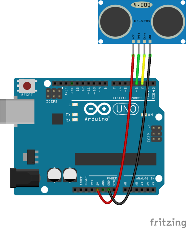
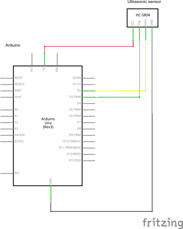
(Die Seite wurde neu angelegt: „== Anschluss des HC-SR04 an den Arduino == zum Anschluss des HC-SR04 Ultraschallsensor an ein Arduino Board werden 2 Digital I/Os benötigt. Ein Trigger A…“) |
K (→Simulation) |
||
| (5 dazwischenliegende Versionen desselben Benutzers werden nicht angezeigt) | |||
| Zeile 9: | Zeile 9: | ||
== Programm für den Arduino == | == Programm für den Arduino == | ||
| − | <syntaxhighlight lang=" | + | Das Arduino Programm liest zyklisch den Ultraschallsensor aus, rechnet die gemessene Pulsbreite in cm um und gibt die Entfernung zum Objekt über die [[UART |serielle Schnittstelle]] aus. |
| + | |||
| + | <syntaxhighlight lang="Arduino"> | ||
#define TRIGGER_PIN 3 | #define TRIGGER_PIN 3 | ||
#define ECHO_PIN 2 | #define ECHO_PIN 2 | ||
long duration; | long duration; | ||
| − | long cmMsec | + | long cmMsec; |
void initHCSR04() | void initHCSR04() | ||
| Zeile 38: | Zeile 40: | ||
} | } | ||
| − | |||
| − | |||
| − | |||
| − | |||
| − | |||
| − | |||
| − | |||
| − | |||
| − | |||
long microsecondsToCentimeters(long microseconds) | long microsecondsToCentimeters(long microseconds) | ||
{ | { | ||
| Zeile 55: | Zeile 48: | ||
} | } | ||
| − | |||
| − | |||
| − | |||
| − | |||
| − | |||
| − | |||
| − | |||
| − | |||
| − | |||
| − | |||
| − | |||
| − | |||
| − | |||
void setup(){ // Serial initialization | void setup(){ // Serial initialization | ||
Serial.begin(9600); // Sets the baud rate to 9600 | Serial.begin(9600); // Sets the baud rate to 9600 | ||
| − | |||
initHCSR04(); | initHCSR04(); | ||
} | } | ||
| Zeile 79: | Zeile 58: | ||
cmMsec = microsecondsToCentimeters(duration); | cmMsec = microsecondsToCentimeters(duration); | ||
| − | |||
Serial.print("CM: "); | Serial.print("CM: "); | ||
Serial.print(cmMsec); | Serial.print(cmMsec); | ||
| − | |||
| − | |||
delay(50); | delay(50); | ||
} | } | ||
</syntaxhighlight> | </syntaxhighlight> | ||
| + | |||
| + | == Simulation == | ||
| + | |||
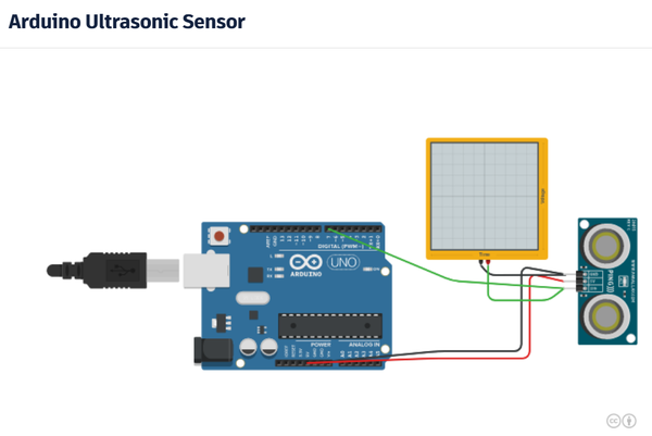
| + | Es gibt eine Simulation für [[TinkerCAD Circuits]]. Hier wird allerdings ein Ping Sensor verwendet. Am Ausgangssignal des Sensors hängt ein Oszilloskop. Klickt man bei laufender Simulation auf den Sensor, kann man mit der Maus das Objekt (Kugel) vor dem Sensor bewegen und dabei beobachten, wie sich das Signal am Ausgang ändert. | ||
| + | |||
| + | [[File:Tinkercad-Arduino-Ping.png|600px|Tinkercad Simulation - Arduino Ping]] | ||
| + | |||
| + | |||
| + | [https://www.tinkercad.com/things/3aTIRVV2V6v-arduino-ultrasonic-sensor| Tinkercad Circuits - Arduino Utraschall Sensor] | ||
[[Category:Elektronik]] | [[Category:Elektronik]] | ||
[[Category:Sensoren]] | [[Category:Sensoren]] | ||
[[Category:Arduino]] | [[Category:Arduino]] | ||
Aktuelle Version vom 21. Februar 2018, 23:59 Uhr
Anschluss des HC-SR04 an den Arduino
zum Anschluss des HC-SR04 Ultraschallsensor an ein Arduino Board werden 2 Digital I/Os benötigt. Ein Trigger Ausgang, der den Sende Burst startet. Sowie ein Echo Eingang, der das empfangene Echo Signal einlist. Zur Auswertung wird die Länge des Echo Impulses gemessen, um darüber die Laufzeit und damit die Entfernung zum Objekt zu bestimmen.
Programm für den Arduino
Das Arduino Programm liest zyklisch den Ultraschallsensor aus, rechnet die gemessene Pulsbreite in cm um und gibt die Entfernung zum Objekt über die serielle Schnittstelle aus.
#define TRIGGER_PIN  3
#define ECHO_PIN     2

long duration;
long cmMsec;

void initHCSR04()
{
  pinMode(TRIGGER_PIN, OUTPUT);
  pinMode(ECHO_PIN, INPUT);
  digitalWrite(TRIGGER_PIN, LOW);
}

long readHCSR04()
{
  long pulsein;
  // The HC-SR04 is triggered by a HIGH pulse of 10 or more microseconds.
  digitalWrite(TRIGGER_PIN, HIGH);
  delayMicroseconds(10);
  digitalWrite(TRIGGER_PIN, LOW);

  // The same pin is used to read the signal from the HC-SR04 a HIGH
  // pulse whose duration is the time (in microseconds) from the sending
  // of the ping to the reception of its echo off of an object.
  pulsein = pulseIn(ECHO_PIN, HIGH);
  return pulsein;
}

long microsecondsToCentimeters(long microseconds)
{
  // The speed of sound is 340 m/s or 29 microseconds per centimeter.
  // The ping travels out and back, so to find the distance of the
  // object we take half of the distance travelled.
  return microseconds / 29 / 2;
}

void setup(){                                 // Serial initialization
  Serial.begin(9600);                         // Sets the baud rate to 9600
  initHCSR04();
}

void loop()
{
  duration = readHCSR04();

  cmMsec = microsecondsToCentimeters(duration);

  Serial.print("CM: ");
  Serial.print(cmMsec);

  delay(50);
}
Simulation
Es gibt eine Simulation für TinkerCAD Circuits. Hier wird allerdings ein Ping Sensor verwendet. Am Ausgangssignal des Sensors hängt ein Oszilloskop. Klickt man bei laufender Simulation auf den Sensor, kann man mit der Maus das Objekt (Kugel) vor dem Sensor bewegen und dabei beobachten, wie sich das Signal am Ausgang ändert.


