I2C-LCD am Arduino: Unterschied zwischen den Versionen
(Die Seite wurde neu angelegt: „== Anschluss des HC-SR04 an den Arduino == zum Anschluss des I2C-LCD Moduls an ein Arduino Board werden die beiden I2C I/Os benötigt. File:I2C-LCD_wi…“) |
(→Programm für den Arduino) |
||
| (Eine dazwischenliegende Version desselben Benutzers wird nicht angezeigt) | |||
| Zeile 1: | Zeile 1: | ||
== Anschluss des HC-SR04 an den Arduino == | == Anschluss des HC-SR04 an den Arduino == | ||
| − | zum Anschluss des [[I2C | + | zum Anschluss des [[I2C LCD Modul]] an ein Arduino Board werden die beiden I2C I/Os benötigt. |
[[File:I2C-LCD_wiring.png|600px|I2C-LCD Verdrahtung]] | [[File:I2C-LCD_wiring.png|600px|I2C-LCD Verdrahtung]] | ||
| Zeile 10: | Zeile 10: | ||
Das Arduino Programm gibt Testausgaben auf dem LCD-Modul aus. | Das Arduino Programm gibt Testausgaben auf dem LCD-Modul aus. | ||
| − | Je nach verwendetem I2C Extender wird | + | Je nach verwendetem I2C Extender wird LiquidTWI2 Bibliothek benötigt. |
<syntaxhighlight lang="Arduino"> | <syntaxhighlight lang="Arduino"> | ||
| + | // include the library code: | ||
| + | #include <Wire.h> | ||
| + | #include <LiquidTWI2.h> | ||
| + | // Connect via i2c, default address #0 (A0-A2 not jumpered) | ||
| + | LiquidTWI2 lcd(0); | ||
| + | // Creat a set of new characters | ||
| + | const uint8_t charBitmap[][8] = { | ||
| + | { 0xc, 0x12, 0x12, 0xc, 0, 0, 0, 0 }, | ||
| + | { 0x6, 0x9, 0x9, 0x6, 0, 0, 0, 0 }, | ||
| + | { 0x0, 0x6, 0x9, 0x9, 0x6, 0, 0, 0x0 }, | ||
| + | { 0x0, 0xc, 0x12, 0x12, 0xc, 0, 0, 0x0 }, | ||
| + | { 0x0, 0x0, 0xc, 0x12, 0x12, 0xc, 0, 0x0 }, | ||
| + | { 0x0, 0x0, 0x6, 0x9, 0x9, 0x6, 0, 0x0 }, | ||
| + | { 0x0, 0x0, 0x0, 0x6, 0x9, 0x9, 0x6, 0x0 }, | ||
| + | { 0x0, 0x0, 0x0, 0xc, 0x12, 0x12, 0xc, 0x0 } | ||
| + | |||
| + | }; | ||
| + | |||
| + | void setup() | ||
| + | { | ||
| + | int charBitmapSize = (sizeof(charBitmap ) / sizeof (charBitmap[0])); | ||
| + | |||
| + | lcd.setMCPType(LTI_TYPE_MCP23008); | ||
| + | lcd.begin(16,4); // initialize the lcd | ||
| + | |||
| + | for ( int i = 0; i < charBitmapSize; i++ ) | ||
| + | { | ||
| + | lcd.createChar ( i, (uint8_t *)charBitmap[i] ); | ||
| + | } | ||
| + | |||
| + | lcd.home (); // go home | ||
| + | lcd.print("Hello, ARDUINO "); | ||
| + | lcd.setCursor ( 0, 1 ); // go to the next line | ||
| + | lcd.print (" FORUM - fm "); | ||
| + | delay ( 1000 ); | ||
| + | } | ||
| + | |||
| + | void loop() | ||
| + | { | ||
| + | lcd.home (); | ||
| + | // Do a little animation by writing to the same location | ||
| + | for ( int i = 0; i < 2; i++ ) | ||
| + | { | ||
| + | for ( int j = 0; j < 16; j++ ) | ||
| + | { | ||
| + | lcd.print (char(random(7))); | ||
| + | } | ||
| + | lcd.setCursor ( 0, 1 ); | ||
| + | } | ||
| + | delay (200); | ||
| + | } | ||
</syntaxhighlight> | </syntaxhighlight> | ||
[[Category:Elektronik]] | [[Category:Elektronik]] | ||
[[Category:Arduino]] | [[Category:Arduino]] | ||
Aktuelle Version vom 11. Mai 2018, 13:58 Uhr
Anschluss des HC-SR04 an den Arduino
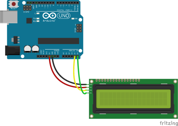
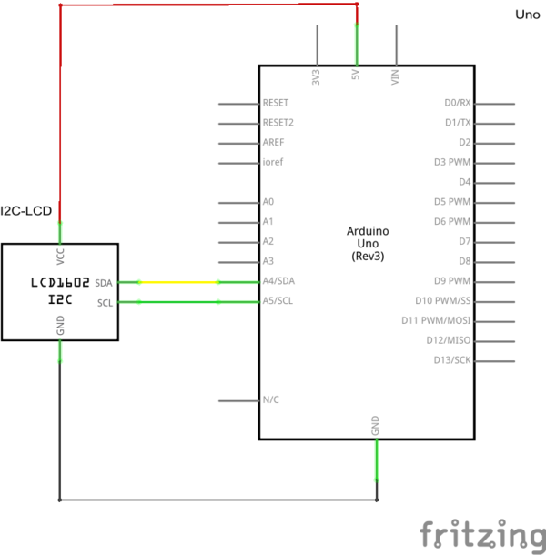
zum Anschluss des I2C LCD Modul an ein Arduino Board werden die beiden I2C I/Os benötigt.
Programm für den Arduino
Das Arduino Programm gibt Testausgaben auf dem LCD-Modul aus. Je nach verwendetem I2C Extender wird LiquidTWI2 Bibliothek benötigt.
// include the library code:
#include <Wire.h>
#include <LiquidTWI2.h>

// Connect via i2c, default address #0 (A0-A2 not jumpered)
LiquidTWI2 lcd(0);
// Creat a set of new characters
const uint8_t charBitmap[][8] = {
   { 0xc, 0x12, 0x12, 0xc, 0, 0, 0, 0 },
   { 0x6, 0x9, 0x9, 0x6, 0, 0, 0, 0 },
   { 0x0, 0x6, 0x9, 0x9, 0x6, 0, 0, 0x0 },
   { 0x0, 0xc, 0x12, 0x12, 0xc, 0, 0, 0x0 },
   { 0x0, 0x0, 0xc, 0x12, 0x12, 0xc, 0, 0x0 },
   { 0x0, 0x0, 0x6, 0x9, 0x9, 0x6, 0, 0x0 },
   { 0x0, 0x0, 0x0, 0x6, 0x9, 0x9, 0x6, 0x0 },
   { 0x0, 0x0, 0x0, 0xc, 0x12, 0x12, 0xc, 0x0 }

};

void setup()
{
   int charBitmapSize = (sizeof(charBitmap ) / sizeof (charBitmap[0]));

  lcd.setMCPType(LTI_TYPE_MCP23008);
  lcd.begin(16,4);               // initialize the lcd

   for ( int i = 0; i < charBitmapSize; i++ )
   {
      lcd.createChar ( i, (uint8_t *)charBitmap[i] );
   }

  lcd.home ();                   // go home
  lcd.print("Hello, ARDUINO ");
  lcd.setCursor ( 0, 1 );        // go to the next line
  lcd.print (" FORUM - fm   ");
  delay ( 1000 );
}

void loop()
{
   lcd.home ();
   // Do a little animation by writing to the same location
   for ( int i = 0; i < 2; i++ )
   {
      for ( int j = 0; j < 16; j++ )
      {
         lcd.print (char(random(7)));
      }
      lcd.setCursor ( 0, 1 );
   }
   delay (200);
}
